Kinematics
Background and Terminology
Kinematics is the study of how things move. In particular, desire methods for precisely calculating the position of points on a manipulator (static kinematics), and model how they will change as each joint moves (dynamic kinematics). Further, we need to know which joint values will achieve a desired position (inverse kinematics) in order to produce controlled motions.
Manipulators are constructed from a series of links, each connected by an actuator. A series of links is also called a “chain”, with one end defined as the “base”, and the other called the “end effector”. Actuators are commonly either “revolute” joints which cause rotation about an axis, or “prismatic” which cause translation along an axis.
Commonly, inverse kinematic algorithms solve only for the end effector position, where an industrial robot would have a gripper. We have generalized the inverse kinematic solution so that you can solve for any point on (or off) of a link, and not just the center of the end effector, which will allow you to do manipulation with any surface of the robot.
Overview
The Kinematics class provides the recommended interface for kinematics computation. This class interfaces Tekkotsu's data structures with the lower level KinematicJoint class, which does the algorithmic heavy lifting (with the help of the fmat matrix library and the IKSolver subclasses).
There is a global instantiation of Kinematics, called kine, which always references the current values of WorldState. Kinematics also serves as the base class for the PostureEngine class, so any time you have a PostureEngine or subclass thereof, you will be able to call the Kinematics functions on it to perform calculations regarding the pose it represents.
 The types of calculations provided by Kinematics include forward kinematics (computing a point location from a set of joint values), ground plane estimation, and ray projection. In addition, the PostureEngine class adds inverse kinematics (computing a set of joint values to reach a point location).
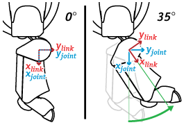
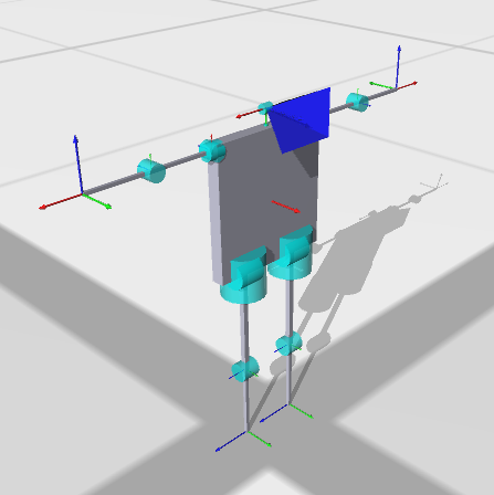
Note that there are two reference frames associated with each actuator - a static joint frame and a mobile link frame. (Figure at right) There is a link frame and a joint frame version of many of the functions. The joint frame is constant for a given joint, whereas the link frame rotates with the joint. In other words, points physically attached to the link are always at the same location in the link frame, but move in the joint frame as that joint moves.
In practice, you will almost always want to use the link frame.
Usage
Implementation reference documentation is found in the Kinematics and PostureEngine classes, although you can also access the KinematicJoint class directly, as is done by the look*() functions of HeadPointerMC.
fmat's matrices are used for representing and manipulating position and orientation. Points are represented with column vectors, orientations are 3x3 matrices, and combined affine transformations by the specialized fmat::Transform.
The fmat namespace provides a number of functions for computing various linear algebra operations and transformations. For instance, to find a 3x3 matrix representing a rotation of 0.2 radians around the x axis, you could call fmat::rotateX(0.2).
The Kinematics class provides two convenience functions for putting coordinates in and out of fmat::Columns, Kinematics::pack(x,y,z) and Kinematics::unpack(x,y,z). Of course you can also create and manipulate fmat::Column directly, and there is also a similar fmat::pack.
Working with these matrices will require some basic knowledge of matrix algebra. Although it's no substitute for a class on the subject, here's a quick refresher:
- A rotation matrix is a 3x3 matrix. Each column is a unit vector, and can also be interpreted as the x, y and z vectors of the coordinate frame that will result after the rotation is applied.
- A transformation matrix is a 4x4 matrix. The upper left 3x3 is the rotational component of the transformation, and the 4th column holds the translational offset. The bottom row (in standard form) is [0 0 0 1].
- A homogeneous vector has four entries - the extra component holds the scaling of the vector. Some examples:
-
- [1 2 3 1]' => (1, 2, 3)
- [1 2 3 2]' => (1/2, 2/2, 3/2) = (0.5, 1, 1.5)
- [1 2 3 .1]' => (1/.1, 2/.1, 3/.1) = (10, 20, 30)
- [1 2 3 0]' -> an infinite ray pointing along [1 2 3]
- To convert a point p using the transformation T, multiply the transformation by the point from the right, as in: T*p.
-
- Remember that matrix operations are not commutative. In other words, A*B does not equal B*A. (In fact, may not even be a legal operation unless they are both square.)
- Remember that matrix operations are not commutative. In other words, A*B does not equal B*A. (In fact, may not even be a legal operation unless they are both square.)
- To find the inverse of a rotation matrix, you can just take the transpose (At = A.transpose()). However, to find the inverse of a full transformation matrix, you need to take the full inverse (Ai = invert(A)).
Initialization and Configuration
By default the kinematic configuration is stored in project/ms/config/modelname.kin, which is read by kine when Tekkotsu launches. The runtime configuration file, project/ms/config/tekkotsu.xml, is what actually controls which file is loaded, but there is little reason to change it from the default modelname.kin setting.
The .kin file is a Property List format XML file, using the Denavit-Hartenberg convention (explained below) to specify the placement of joint reference frames in a convenient way for forward and inverse kinematic calculations. There should be some documentation at the beginning of the file:
There are five parameters which determine the location and motion of each joint, and one we include for convenience:
- JointType - Indicates the type of motion produced by the joint
One of revolute or prismatic- d - Displacement along the previous joint's z axis
- θ - Rotation about the previous joint's z axis (theta, U+03B8)
- r - Displacement from prev. z along the current joint's x axis
- α - Rotation about the current joint's x axis (alpha, U+03B1)
- qOffset - An additional parameter which shifts the final reference frame to the physical joint's 0 position. This is a rotation about the joint's z axis for revolute joints, or transation along z for prismatic. (not strictly necessary, but sometimes convenient to use)
In other words, θ and d align the previous joint's x axis with the current joint's x axis, and then a displacement of r (radius of rotation about parent z, translates out along x) defines the current joint's origin. α then orients the current joint's z axis (the axis of actuation).
Some additional settings used by inverse kinematics:
- Min: The minimum acceptable joint value for inverse kinematics
- Max: The maximum acceptable joint value for inverse kinematics Inverse kinematics ignores this joint if Min==Max (immobile).
Other parameters are used for graphics and physics modelling, and described on the Mirage page.
All distances are in millimeters. Angles are radians, unless a 'unit' attribute is specified in the XML tag, or a '°' is suffixed. You can also specify radians as multiples of Pi, e.g. 'π/2'. Note that since unit suffixes are non-numeric characters, using them in <real> tags is not compatible with most plist parsers; in this case use the <string> value tag instead. Tekkotsu's parser is happy either way.
Denavit-Hartenberg Parameters
The use of Denavit-Hartenberg parameters are illustrated in the following video:
The good news is that as a user, you don't generally need to worry about this other than perhaps getting a feel for why joint origins are not always in intuitive locations. If you are designing a new robot however, you may need to understand these parameters in order to model the robot’s motion via the kinematics system. Even then, we have a tool to help you calculate the DH parameters from a series of global coordinates.
An Example
In the video above, we implied the first joint frame would be used as the base frame for the “arm”. However, for a statically mounted system as this, it may be more practical to place the base frame on the ground so z=0 is the ground plane. In this case we will define three separate frames: the base, joint 1, and joint 2.
The center of the arm is 36.25 mm above the ground. The link is 100 mm long down its median, where the terminal motor is a total of 92.5 mm above the ground and at a 45° angle.
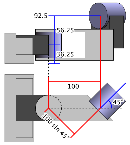
From these measurements and knowledge of the joint orientations, we can determine:
| d | θ | r | α | |
|---|---|---|---|---|
| Base Frame | 0 | 0 | 0 | 0 |
| Joint 1 | 36.25 | 0 | 0 | 0 |
| Joint 2 | 92.5 - 36.25 = 56.25 | -45° | 100 sin 45° = 70.711 | -90° |
However, calculating these values by hand can be time consuming. Therefore, we include a tool in Tekkotsu/tools/dhcalc which will calculate the D-H parameters for you, and produce a .kin file ready to drop in your project. To build the tool, change to the dhcalc directory, then type make. When run, dhcalc will read a series of joint coordinates form standard input, and write the corresponding kinematics file on standard output. Use shell redirection to pipe this data to and from files.
You can use the -h option for more documentation on the input and output, but basically you list the name, origin, and either z‑axis vector or an XYZ Euler rotation. For our sample, we would input:
Any point along the z axis is sufficient for the Origin point, although dhcalc will attempt to match the specified points when it has underconstrained links. When modeling in 3D software, you would probably record the center of the joint, but if measuring a physical model, you may find it more feasible to gauge an accessible point on the surface. In either case, dhcalc will output:
On standard error, dhcalc also reports:
This is because, in this case, the joint frame could not be placed at the origin specified in the input. If you have a graphical model you wish to export for Mirage, this lets you know how to offset the origin of the model so it will be placed correctly in the virtual environment. This can usually be applied to the mesh data itself, otherwise you can use the ModelOffset parameter in the kinematics file, described further with the LinkComponent parameters on the Mirage page.
Notice a lot of the “clutter” in the kinematics output is from graphical components which are automatically inserted. This allows you to immediately display in Mirage without constructing a custom 3D model. Of course, if you do produce such a model you can easily replace the automatically generated components. There are also options for dhcalc to estimate mass values and/or display directly in Mirage, as shown:
There is also a sample humanoid input file included with dhcalc:
The comments in the humanoid sample also cover a few tweaks sometimes necessary when you want a reference frame to be in a specific place and orientation, such as a camera, where the orientation of the x axis needs to be placed by means other than the “natural” D-H layout.